|
|
| With the LCS the US Navy wanted a high-speed vessel that
could work in shallow water. The model of the 1/96 scale LCS-3 that is
described here was built for my employer, Lockheed Martin. The main challenge
here is getting the model built before the deadline and getting it done
under budget. Those two things are more important that the level of detail,
Im sad to say. After figuring out how much the material would cost, and
knowing my hourly rate, I would have to finish this model in 240 hours
to keep to the budget. That comes out to 6 weeks if I work 40-hour weeks.
The only problem is I had 4 weeks to get it done to make the deadline.
Over time I have become comfortable building models the way that is described
below, and comfort equals speed so no experimenting here with a new way
to do things. I will do my best to keep this interesting but I dont consider
myself a good writer so this may turn into a real drudgery to get through.
If you persevere, you might find something that can help you in your own
projects. |
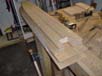
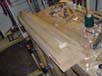
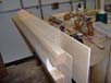
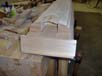
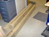
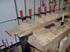
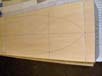
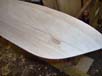
| The first photo shows how the basswood looks when I get it from the
lumberyard. It is pretty rough and it does not have uniform width or height. |
 |
| A piece is in the vices and one edge is planed flat and straight so
it can be cut into lifts on the band saw. |
 |
| The lifts are generally ½ thick and they are used to build
up the hull in stages at different deck levels. |
 |
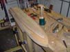
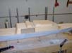
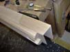
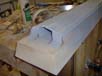
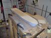
| This photo shows how the lifts look during glue up. To the left the
cut out for the water jets can be seen on the bottom lift. The space above
that will be the boat launching area and the thin piece that sticks way
out to the left on top will become the flight deck. |
 |
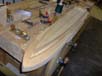
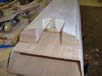
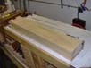
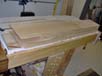
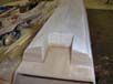
| With the future hull out of the clamps, the piece that will be the
floor of the boat handling area and the sloped deck at the bow of the ship
are added. |
 |
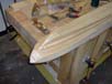
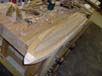
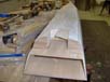
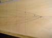
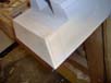
| The piece of wood that was added at the bow is worked into
the sloped deck and the hull is turned over. The centerline of the hull
is marked all the way around the block of wood and the inboard edges of
the spray chines are drawn on the bottom of the hull. |
 |
 |
| The outline of the deck gets added next. |
 |
| That completes what has to be marked on the top and bottom of the hull. |
 |
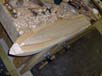
| Now a trip to the band saw and I get a rough shape of the
hull. The level of the outboard spray chine is added to the side of the
hull. The line drawn on the bottom of the hull and the line on the side
are used to cut a rabbet into the hull that will become the chine. By keeping
the side of rabbet at 90 degrees to the bottom of the block of wood and
the bottom at 90 degrees to the side, the chine is right where it needs
to be and it is very easy to fair with so much wood to support the tools. |
 |
 |
| These photos show how the bulk of the wood is hogged out
with gouges and then smoothed with a rabbet block plane and a carriage
plane to finish the other three chines. |
|
|
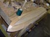
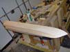
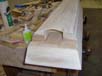
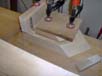
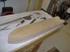
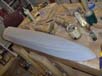
| The shape of the bow is cut into the hull next and the
centerline is drawn on to the new surface. Now the real carving begins.
The outboard edges of the chines are drawn on and it is a matter of removing
wood so I get a straight line from the keel to the inboard edge of the
bottom chine, from the outboard edge of the bottom chine to the inboard
edge of the top chine, and from the outboard edge of the top chine to the
edge of the deck.
Most of the waste is removed with gouges and then worked smooth with planes,
rasps, and sanding blocks.
There is not much need for contour gauges on this hull form except at the
bow. Over 90% of the hulls contour is checked with a six-inch ruler. |
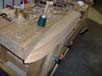
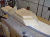
| The sides of the boat handling area are added. There is a rabbet at
the forward edge so that there is more than an end grain to end grain glue
joint. |
 |
| How the rabbets are made will be covered in the future, that is not
the only one. The anchor pocket is next. |
 |
| The bottom of the hull that makes the tunnel for the inboard water
jets and the transom is added. |
 |
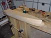
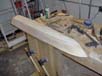
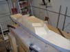
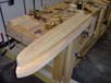
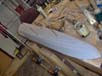
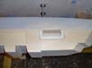
| Now I have a finished hull form that is ready for the boat
doors on the starboard side and transom or do I? The answer is no!
That is how it is when you build a model of a ship that is under construction.
The anchor pocket has to be moved up so that it will be above the chines,
not between them and I have to make the back of the hull longer. At least
no more progress was made before these changes had to be made. The transom
had to be removed and wood was glued to the inside of the boat handling
area on all four sides so the wood that will be added to make the extension
will have long grain to glue to and not rely on an end grain to end grain
joint.
|
| The finished extension is seen in photo 34. This extension and the
outboard water jets having already been moved farther back make up for
the bouncy tanks that were added to LCS-1. |
 |
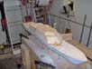
| The fashion plates are added and some other bitts as well. The time
to make the changes has eaten up the time that would have gone into making
the open boat doors and extra wood was added to the inside of that space,
so the doors will have to stay closed. |
 |
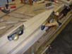
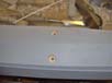
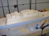
| Holes for the all thread are drilled into the hull and
shoulders are added so all of them are the same depth. When the model gets
mounted to the permanent base, all four support posts can be made the same
length. |
 |
 |
| The all thread gets epoxied into the holes. |
 |
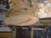
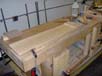
| The epoxy is hard and the hull is mounted to the base that it will
be mounted to during the rest of the build. You can see the start of the
deckhouse to the right of the hull and the repositioned anchor pocket. |
 |
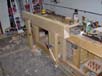
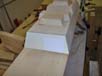
| The next photos show the progression of how the deckhouse
is built up. At the start when all of the lifts for the hull were made,
the deckhouse lifts were also made. The lift for the lowest deckhouse level
was not made full length because the helo hangar was to be open. That is
why you see the open space that has to be covered over. It would have been
much easier to make it solid now that the hangar is closed. |
|
|
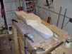
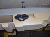
| The cut out for the port side boat is next. A drill is used to remove
a good amount of wood and set the depth of the hole. |
 |
| A mortis chisel is used next to hog out the bulk of what is left. A
bevel edge chisel is then used to get the sides of the hole square and
straight and smooth. The bottom of the hole is impossible to get smooth
so a thin piece of wood is cut to fit and glued to the bottom of the hole
to cover up all of the boo-boos. A shoulder is cut around the opening to
accept the sheet of plywood that will become the finished opening. The
shoulder is cut with a router. |
 |
| The kind that was popular before tool companies started to put power
cords and rechargeable batteries on such things. |
 |
| With the shoulders done, its time to put the wood in place. |
 |
| The hangar door is next. |
 |
| The back bulkhead is .060 thick plastic and the door itself is .040
Evergreen siding sheet. |
 |